OPEN SOLAR TRAILER

OPEN DESIGN / 17 SEPTEMBER 2026

From sunlight
to camp power.

Three connected design drafts document how the trailer will collect, store and distribute energy, with the proposed protection and bonding network. One Victron inverter links the DC system to the 120 V camp circuits.

Design review only. These are functional architectures. Exact devices, wiring, protection coordination and bonding still need qualified review before construction or energizing.

Planning and procurement: download the v06 priced BOM (.xlsx). PG-04 identifies an unselected, unpriced DC/PV ground-fault arrangement; bonding hardware also needs reconciliation against the existing allowance. The current total has not been revised for those selections. The architecture drafts do not establish final component costs or tested performance.

DC-02 / DESIGN-REVIEW DRAFT

Solar, storage and the DC bus

Download DC-02 (.md)

Status: design-review draft — not a construction drawing.

Basis: owner-supplied DC-02, with its Victron equipment explicitly selected by the owner on 17 September 2026. Two SmartSolar MPPT 150/35 controllers; two 51.2 V, 100 Ah batteries in parallel; a MultiPlus-II 48/5000/70, 120 V inverter/charger. Exact battery compatibility remains unconfirmed.

This sheet defines connection roles, polarity, monitoring boundaries, and protective functions. It does not specify cable gauges, fuse ratings, terminal layouts, grounding/bonding, or physical installation order. Protecting and isolating a circuit may require several devices; a block is not necessarily a single purchased part.

The companion AC-03 architecture describes the inverter's AC-out-1 distribution and optional AC-in shore path. Its AC neutral is separate from the DC-negative nodes defined here.

PG-04 adds the protection and bonding draft. The DC/PV ground-fault arrangement remains unselected; it does not approve a hard jumper from N1 to chassis.

A. Solar-input architecture

Each arrow represents a positive-and-negative PV circuit, not a single wire. Only like polarities join at the parallel junctions. R1–R4 are roof panels; L1–L2 and W1–W2 are the two panels on each side. PV protection selection remains a design-review item.
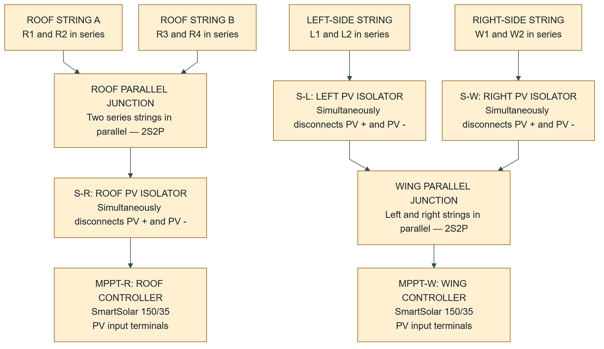
Roof: two series pairs combine through the roof isolator into the roof MPPT. Left and right wing series pairs each have an isolator, then combine into one shared wing MPPT.
DC-02 · Solar inputs. Scroll to explore on small screens.Open full-size diagram

The roof and wing PV circuits stay separate. Their controller battery outputs connect to the common DC distribution in Section C; the PV circuits do not connect directly to the battery bus.

Either complete wing-side string can remain connected while the other is isolated. This does not give each individual panel independent charging capability. Both wing sides share one tracker.

B. Battery-bank architecture

These are connection paths, not directional energy arrows. A battery block has distinct positive and negative terminals. P0, P1, N0, and N1 are different electrical junctions, not interchangeable names for one bus.

Crossing lines without a labeled junction do not represent an electrical connection.
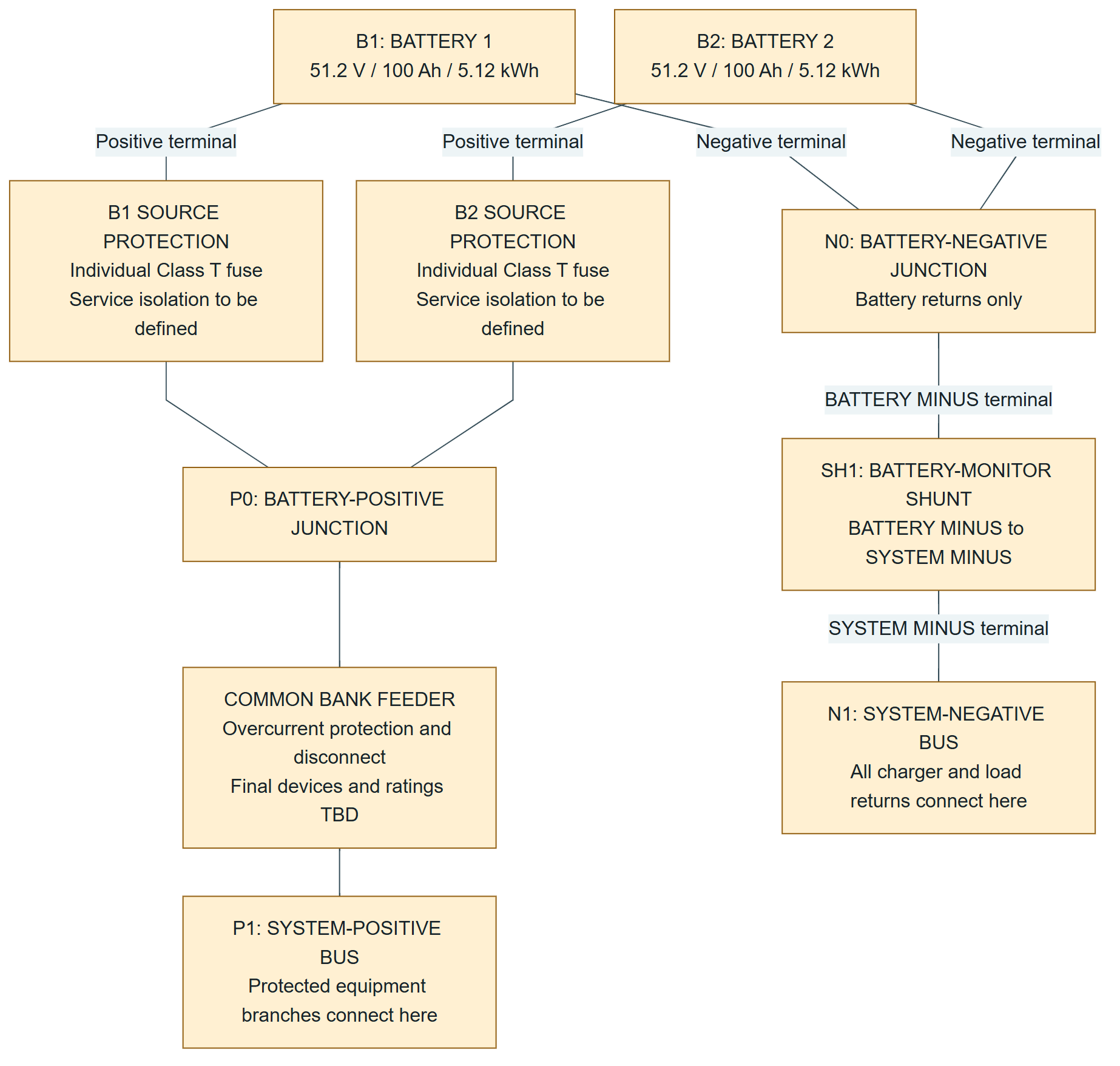
Each battery positive passes through an individual fuse to P0, then common bank protection to P1. Battery negatives meet at N0, pass through the SmartShunt, and reach N1, where all load and charger returns connect.
DC-02 · Battery bank and monitoring boundary. Scroll to explore on small screens.Open full-size diagram

The parallel bank remains 51.2 V nominal, with 200 Ah / 10.24 kWh nominal capacity. These are not two batteries connected in series.

P0 and N0 identify battery-combining junctions, not a commitment to buy a separate busbar product for every labeled node. The combined battery feeder must be protected for the combined available fault current; coordination with the individual battery fuses is unresolved.

The shunt's small fused Vbatt+ supply is listed below; it is not a high-current connection through the shunt's negative terminals.

C. Equipment connections to the common buses

MPPT-R and MPPT-W below are the SAME TWO controllers shown in Section A.

Equipment / terminal Positive connection Negative connection Role
MPPT-R battery terminals BAT+ to P1 through its own battery-side overcurrent protection and isolation BAT- to N1 Roof charging
MPPT-W battery terminals BAT+ to P1 through its own battery-side overcurrent protection and isolation BAT- to N1 Wing charging
Inverter/charger DC terminals DC+ to P1 through its protected, isolatable inverter branch DC- to N1 Draws DC for 120 V loads; can return charging energy when approved optional AC input is installed
Optional 48 V-to-12 V converter input Input+ to P1 through its own protection and isolation Input- to N1 Supplies a separate, protected 12 V distribution system
SmartShunt monitor supply Small manufacturer-specified fused lead from battery positive / P0 to Vbatt+ Reference is through its installed shunt; no added bypass Keeps battery monitoring powered

Each MPPT requires protection on its BATTERY side, even though its PV input also has an isolator. PV and battery-side protection have different jobs. See the manufacturer manuals before selecting any devices.

D. Required design notes

Shunt boundary

Both battery negatives connect only to N0, then through SH1 to N1. The negative connections of the inverter, both MPPT battery outputs, and all other DC loads/chargers belong on N1. Do not add a normal-current path that bypasses the shunt.

The shunt measures NET energy entering and leaving the battery bank. Solar energy that feeds a load directly at the system buses is not battery throughput. Use controller data and separate load metering for total solar generation and delivered-load measurements.

Battery disconnect is not an all-source shutdown

Opening the common bank disconnect does not establish that the system bus is de-energized: solar controllers and an optionally shore-powered inverter/charger are additional sources. The fused monitor supply at P0 also remains battery-powered.

For the SmartSolar controllers, Victron prescribes PV off before disconnecting battery power, and battery connected before restoring PV. A complete system shutdown must also account for AC input, loads, and retained energy. Sunlit PV wiring upstream of an open isolator remains a source. This sheet is not a lockout procedure.

Grounding and bonding remain required

This sheet does not release a grounding design. A later protection/bonding sheet must address PV frames, steel mounting rails, trailer chassis, enclosures, DC system grounding, and ground-fault protection. Do not infer a PV-positive or PV-negative chassis connection from these diagrams. Victron specifically says not to ground PV conductors separately.

Battery controls and limits remain open

Confirm the exact batteries, parallel-operation instructions, charge/discharge limits, temperature limits, and compatible shutdown/control method. Account for BOTH MPPTs and optional inverter charging together, including operation if one battery is unavailable. No battery communications link, coordinated BMS shutdown, or current limit is asserted by this diagram.

No 12 V equipment connects directly to the 51.2 V bank. No direct trailer-bank connection to the golf-cart battery is included. No alternator connection is included.

Manufacturer reference checks

[S1] Victron SmartSolar 150/35 and 150/45 installation manual — battery-side protection, PV configuration, grounding, and connection sequence. https://www.victronenergy.com/media/pg/Manual_SmartSolar_MPPT_150-35__150-45/en/installation.html

[S2] Victron SmartShunt installation manual — BATTERY MINUS / SYSTEM MINUS boundary and fused Vbatt+ supply. https://www.victronenergy.com/media/pg/SmartShunt/en/installation.html

[S3] Victron SmartSolar operation manual — shutdown and restart procedure, section 6.5. https://www.victronenergy.com/media/pg/Manual_SmartSolar_MPPT_150-35__150-45/en/operation.html

[S4] Victron MultiPlus-II 120 V installation manual — DC fusing, disconnects, and connection requirements. https://www.victronenergy.com/media/pg/MultiPlus-II_120V/en/installation.html

Reference pages checked 17 September 2026. These references support individual connection rules, not approval of this complete custom trailer design.
Back to document index ↑

AC-03 / DESIGN-REVIEW DRAFT

120 V distribution and optional shore power

Download AC-03 (.md)

Project: Open Solar Trailer
Revision: A — 17 September 2026
Status: Design review only — not a construction or cabling release

Design basis

Continue the current project architecture: one Victron MultiPlus-II 48/5000/70-95 120 V model, supplied by the common DC buses on DC-02. The baseline AC loads are one RV outlet and two ordinary charging/camp circuits. Optional shore input remains outside the baseline build. These selections match the current Victron revision of the v06 priced planning BOM.

This sheet proposes the connection functions and circuit allocation. Breaker ratings below are planning selections, not a completed protection study. Exact equipment, conductor sizes, terminal arrangements, enclosures, and installation requirements need qualified review before energizing.

The companion PG-04 documents protective bonding, source-neutral behavior and the unresolved DC/PV ground-fault arrangement. It does not add a downstream neutral-to-PE bond or finalize protection hardware.

A. Power paths

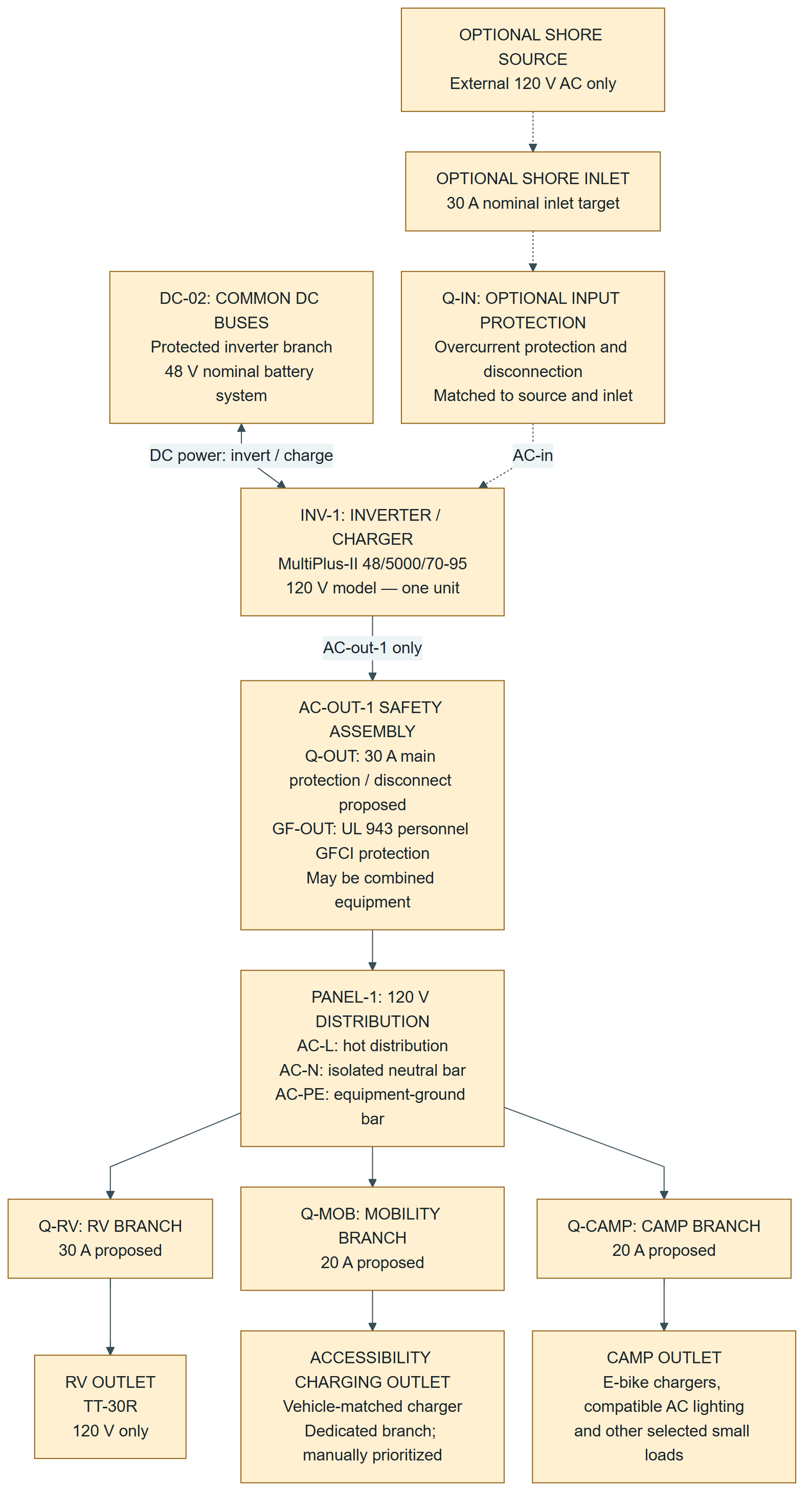
In this diagram, an AC arrow represents a circuit containing L (hot), N (neutral), and PE (protective earth). It is not one conductor. PE continuity is maintained separately from switching, overcurrent, and leakage-sensing functions. Dashed arrows identify optional shore equipment. The bidirectional DC connection is the same connection shown on DC-02, not another inverter.

The DC bus feeds one MultiPlus-II. Optional shore power passes through an inlet and input protection to AC-in. AC-out-1 passes through main and GFCI protection to a panel supplying a 30 A RV branch and separate 20 A mobility and camp branches.
AC-03 · Power paths. Scroll to explore on small screens.Open full-size diagram

AC-out-2 is unused. In normal operation that output is unavailable on battery-only power, so it is not the source for our mobility or camp circuits. AC-out-1 is the intended inverter-backed output. [S1]

The output safety block includes both overcurrent/disconnect and personnel ground-fault functions. Victron's installation instructions specify UL 943-compliant residual-current protection and overcurrent protection in the output path. A generic leakage device is not automatically an equivalent substitute. Final part selection and coordination with the BOM's GFCI receptacles remain open. [S2]

B. Proposed panel schedule

All branches share the same source; their ratings do not add to available output.

ID Function Proposed rating Status
Q-OUT / GF-OUT Main output overcurrent protection, disconnection and personnel GFCI function 30 A overcurrent rating; leakage device selection pending Baseline; arrangement requires review
Q-RV RV TT-30R outlet 30 A Baseline
Q-MOB Dedicated accessibility-charger outlet 20 A Baseline; verify actual charger input
Q-CAMP E-bike charging and selected camp loads 20 A Baseline
Q-IN Shore-input overcurrent protection/disconnect No more than inlet, feeder and source permit; 30 A design target Optional
AC energy meter Measure total energy supplied to the distribution panel Compatible with selected feeder Baseline monitoring; meter wiring not shown

TT-30R is a 30 A, 125 V-rated receptacle for a nominal 120 V circuit; it is not a 240 V outlet. [S6]

Dedicated mobility wiring does not provide automatic load shedding or guarantee uninterrupted charging. Priority means manually stopping discretionary loads before the battery reserve or shared power limit is reached. A common GFCI trip would interrupt all three branches in this arrangement. Protection selectivity and event requirements are review items; protection must not be bypassed to keep a load running.

Optional 12 V sign/lighting/fan circuits remain on DC-02 through their protected converter. They are not duplicated here. AC lighting, when used instead, is included in Q-CAMP's shared load budget.

C. Hot, neutral and protective-earth connections

These are functional connections, not terminal-position or wire-size instructions. Physical left/right terminal positions must come from the exact equipment manual.

Connection Proposed path
INV-1 AC-out-1 L Through Q-OUT/GF-OUT as required by the selected assembly, to AC-L, then each branch breaker and its receptacle hot terminal.
INV-1 AC-out-1 N Through GF-OUT's specified neutral sensing/switching path to the isolated AC-N bar, then the correct neutral path for each branch. Do not create a neutral bypass around a GFCI.
INV-1 PE / chassis ground To the protective-earth network, AC-PE bar, trailer chassis bonding point, panel enclosure and receptacle grounds. No normal load switching or fusing is placed in PE.
Optional shore L Inlet to Q-IN to INV-1 AC-in L. Never to AC-out-1 or an output receptacle.
Optional shore N Inlet to INV-1 AC-in N through any coordinated neutral switching in the selected inlet assembly; no independently fused neutral. Do not jumper inlet neutral directly to the output neutral bar around the inverter.
Optional shore PE Continuous protective-earth connection to the onboard PE/chassis network; not through a relay that opens the protective conductor.

This source-transfer and PE layout follows the MultiPlus's ground-relay/mobile-installation arrangement; terminal-level implementation remains subject to manufacturer and installer review. [S2]

AC-N is not DC-02's N1. AC-N is the AC neutral. N1 is the DC system-negative bus. No direct connection between those two is specified here. DC bonding and the complete chassis/PV grounding plan belong on the later protection-and-bonding sheet.

Use a panel intended for the chosen single-source 120 V arrangement. Do not improvise bus jumpers in a 120/240 V panel unless that use is supported by its listing and manufacturer instructions.

D. Neutral-to-ground bond behavior

For the standard single-inverter arrangement, retain and verify the intended internal ground-relay operation; do not add a permanent neutral-ground bond to the downstream distribution panel. The MultiPlus bonds output neutral to its chassis during standalone inverter operation and opens that relay before accepting an external AC supply. [S2]

Operating condition Neutral-ground arrangement to verify
Battery/solar operation; no accepted external AC Internal inverter ground relay provides the source bond. Downstream AC-N remains isolated from the trailer enclosure and AC-PE.
Accepted shore supply Internal ground relay opens; the external supply must provide the appropriate source grounding/bonding arrangement. No extra panel neutral-ground bond is added.
Any mode Protective-earth continuity and chassis bonding remain intact. Test ground-fault protection in each permitted source mode before service.

Do not assume a floating-neutral generator is interchangeable with a verified shore supply. A future generator connection requires its own source/transfer/bonding review. This sheet does not specify an earth electrode or claim that a ground rod replaces equipment bonding.

E. Shared power limit

The manufacturer's datasheet rates this 48/5000 120 V inverter at 4,000 W at 25°C and 3,700 W at 40°C. “5000” is its VA class, not a 5,000 W continuous rating. [S3]

For our proposed 30 A output main:

  • 120 V x 30 A = 3.60 kVA shared nominal distribution rating, approximately 3.60 kW only at unity power factor. It is not a guaranteed sustained-load allowance.
  • For an ordinary 80%-applied breaker/assembly, a wholly continuous load uses at most 24 A, or 2.88 kVA at 120 V. A 20 A branch similarly provides a 16 A continuous-load planning limit. Mixed continuous/noncontinuous loads require the appropriate sizing calculation. [S5]
  • Operating capacity is limited by the most restrictive of the inverter's W/VA and thermal limits, battery capability, feeder protection, individual branches, connected equipment and available stored energy.

30 A RV + 20 A mobility + 20 A camp does not mean 70 A available. The branch arrangement allows useful connection choices; simultaneous loads must fit the shared limit.

F. Optional shore charging

Shore power enters AC-in. Accepted power can supply AC-out-1 while the charger charges the battery through the same protected DC connection shown on DC-02. [S4]

Set the AC input-current limit to the permitted external source/cord/inlet rating, not the inverter's larger internal transfer rating. Charger settings must also respect the bank's combined limits when solar charging is active. PowerControl manages charging against the input limit; PowerAssist can supplement an external supply with battery energy, but does not change the selected output-main or branch ratings. [S1]

“Charger only” is not an output-isolation mode: accepted shore power can still pass through to AC-out-1. [S4] Baseline construction leaves the optional inlet absent and AC-in unconnected/protected from access. Never feed an output receptacle from another power source, connect output back to input, or use a male-to-male power cord.

G. Items still to close

  1. Exact 120 V panel, breaker and personnel-GFCI hardware, including whole-output versus coordinated downstream protection and costs.
  2. Wire sizes, lengths, ampacity/temperature adjustments, terminal compatibility and weatherproof in-use equipment suitable for event conditions.
  3. Actual mobility charger and simultaneous RV/camp load measurements.
  4. Configuration, transfer/bonding, polarity, ground-fault trip tests and protective-earth continuity checks in every enabled mode.
  5. Separate full protection-and-bonding sheet and a safe all-source shutdown/service procedure. Opening the AC main isolates downstream loads only; it does not make all DC/PV or inverter terminals safe.

These are not already resolved by the BOM's two outdoor GFCI-receptacle allowances. Do not treat this architecture as a priced construction specification or as proof of regulatory compliance.

Sources

Project baseline: Open_Solar_Trailer_Final_Grant_BOM_v06.xlsx, Victron revision dated 17 September 2026 — inverter selection, RV/camp outlets, AC metering and optional shore input. This architecture does not recheck or revise prices.

Manufacturer material checked 17 September 2026. The connection allocation, 30 A output-main target, dedicated mobility branch and common output-GFCI arrangement are proposed design decisions, not statements that the source documents prescribe this exact trailer build.

[S1] Victron Energy, MultiPlus-II 120V — Description, section 2.1 (outputs, PowerControl, PowerAssist): https://www.victronenergy.com/media/pg/MultiPlus-II_120V/en/description.html

[S2] Victron Energy, MultiPlus-II 120V — Installation, especially section 4.4 (AC connections, mobile chassis bonding, ground relay, output protection): https://www.victronenergy.com/media/pg/MultiPlus-II_120V/en/installation.html

[S3] Victron Energy, MultiPlus-II 120V datasheet, 48/5000/70-95 column (inverter real-power ratings): https://www.victronenergy.com/upload/documents/Datasheet-MultiPlus-II-120V-EN-.pdf

[S4] Victron Energy, MultiPlus-II 120V — Operation, section 3.1 (AC-input acceptance and charger-only behavior): https://www.victronenergy.com/media/pg/MultiPlus-II_120V/en/operation.html

[S5] Schneider Electric, FAQ FA104355, 80%- versus 100%-rated breakers (continuous-load application): https://www.se.com/us/en/faqs/FA104355/

[S6] Leviton, product 7313 (TT-30R, 30 A, 125 V): https://leviton.com/products/7313

Back to document index ↑

PG-04 / DESIGN-REVIEW DRAFT

Protection, bonding and grounding

Download PG-04 (.md)

Project: Open Solar Trailer
Revision: A — 17 September 2026
Status: Design-review draft. Not a construction drawing, permit determination, or instruction to energize the system.

Design basis and boundaries

This continues DC-02 and AC-03, without changing the selected architecture: two SmartSolar 150/35 controllers, roof and wing arrays separately wired 2S2P, two 51.2 V batteries in parallel, and one MultiPlus-II 48/5000/70-95 120 V inverter/charger. The optional shore inlet and optional 12 V converter remain optional. [P1, P2]

The tables distinguish the existing project choices, manufacturer requirements, and proposed implementation. A protection block describes a function; it does not necessarily require a separate purchased enclosure. No new protection hardware has been priced on this sheet.

Construction hold: the DC/PV ground-fault protection and system-reference arrangement is not selected. The SmartSolar manual states that these controllers have no internal ground-fault protection and describes an external GFPD/GFDI arrangement for US NEC installations. This must be resolved for the actual mobile installation before approving a DC-negative-to-chassis connection. [M2]

A. Keep three electrical roles distinct

Label Role in this project Connection rule
PE1 / AC-PE Common protective bonding network Connects equipment enclosures, outlet grounds and trailer metalwork. Not a normal load-return conductor.
AC-N 120 V AC neutral Returns AC load current. Downstream neutral remains isolated from panel metal and PE, except for the approved source bond described in Section C.
N1 System-side DC negative Returns DC load and charger current through the battery-monitor shunt. Its single proposed connection to PE is a separate, unresolved DC ground-fault design issue.

Do not install a direct AC-N-to-N1 jumper. Their source references can be related through the approved bonding network; that does not make the conductors interchangeable. P0/P1 (positive) and N0/N1 (negative) retain their meanings from DC-02. [P1, P2]

B. Common equipment-bonding network

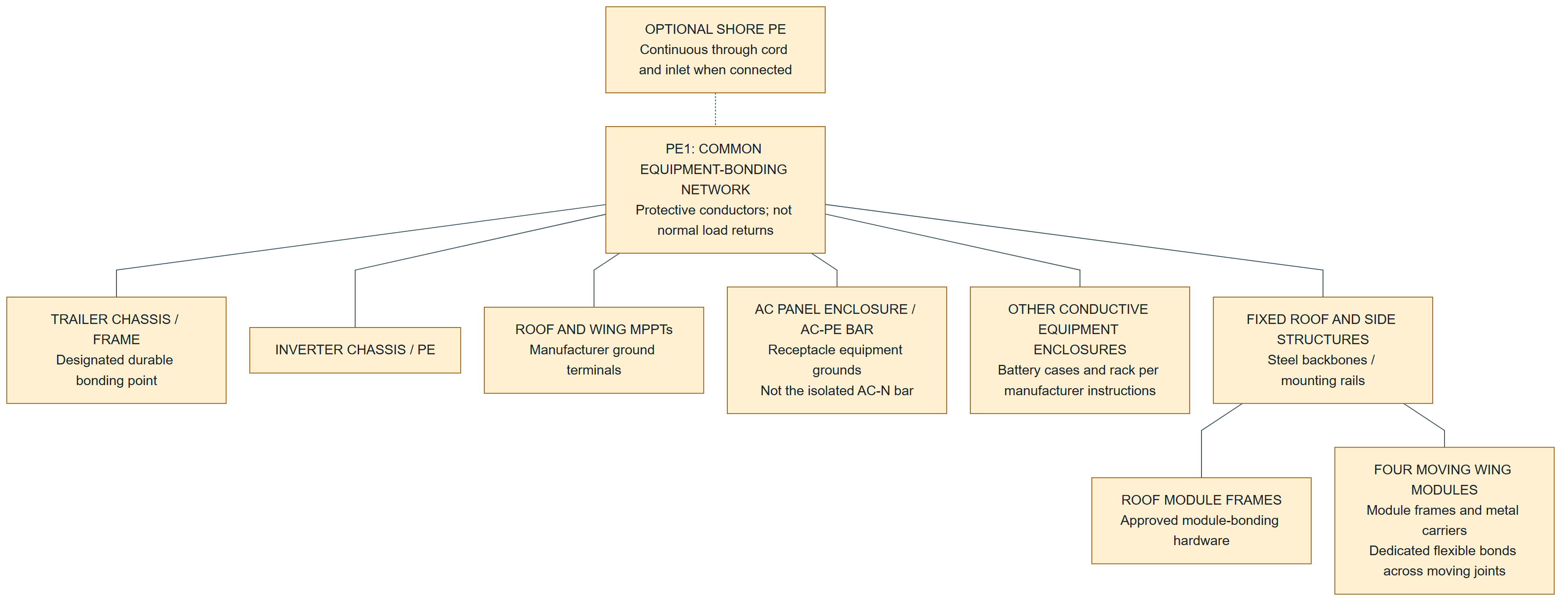
Proposed physical arrangement: a protected PE terminal bar in the equipment compartment, securely bonded to a designated trailer-chassis point, with documented connections to each relevant exposed conductive component. The principle is a continuous, adequately rated, low-impedance fault-return network. [M9]

A common protective bonding network connects the trailer chassis, inverter and controller ground terminals, AC panel and receptacle grounds, equipment enclosures, and roof and wing structures. Each of four moving wing assemblies has a proposed flexible bond. Shore PE is optional; AC neutral is separate.
PG-04 · Equipment bonding. Scroll to explore on small screens.Open full-size diagram

Solid links show proposed bonding paths, not a mandatory star-shaped cable layout. The dashed shore link denotes equipment absent from the baseline, not a switch in PE. Protective conductors run with the circuits they protect where required; physical routing will be specified on the cable sheet.

Trailer-specific design details

I propose a flexible bonding jumper at each of the four moving panel assemblies, with module-to-carrier bonds and fixed-rail-to-chassis bonds documented separately. Do not credit hinges, brace pins, lubricated pivots, painted joints or tow-hitch contact as the sole electrical path. Validate the arrangement through the full folding travel and after transport.

Use module-approved lugs or bonding hardware rather than assuming ordinary mounting bolts establish continuity. Do not improvise extra holes in module frames. Specify corrosion-compatible connections, strain relief and protection from sharp edges, UV and pinching. These are implementation requirements to verify against the final panel and mounting manuals, not an assertion that a particular lug or jumper has already been approved.

Maintain local chassis bonding when the tow vehicle and shore cord are disconnected. Follow the inverter's mobile-installation instructions. [M1] Battery-case grounding terminals, case-to-negative isolation and any internal bonds must be checked before connection; those battery details remain unverified.

No routine switch or fuse is placed in an equipment protective-earth conductor. The specialized DC system-reference/GFDI function below is not an equipment-ground switch. [P2]

C. AC neutral-to-ground behavior

The proposed AC configuration retains the MultiPlus's intended internal ground-relay function. Its configuration manual describes bonding output neutral to the chassis when the AC-input relays are open. [M7]

Mode Source-reference behavior to verify Downstream requirement
Inverter supplies loads; no accepted external AC Internal relay supplies the inverter's neutral-to-PE source bond. AC-N bar remains insulated from the enclosure and AC-PE.
Approved shore AC accepted Internal ground relay opens before AC transfer; the accepted supply must have the appropriate source grounding arrangement. No extra neutral-ground bond in the trailer panel or adapters.
External supply disappears Verify the transfer sequence restores the inverter's intended source reference. Local protective bonding remains intact.

The transfer behavior is described in the installation manual. [M1] These are commissioning requirements, not instructions to manually wire around the relay. Do not bridge AC input and output neutrals around the inverter. A future generator, particularly one with a floating neutral, needs a separate source/bonding review; no bonding-plug solution is assumed. [P2]

AC ground-fault and overcurrent protection

Keep AC-03's Q-OUT/GF-OUT functions downstream of AC-out-1. Victron specifies UL 943-compliant output residual-current protection plus overcurrent protection. [M1] Retain the proposed 30 A output main, 30 A RV branch and two 20 A branches only as project planning selections. [P2]

Select a compatible personnel-GFCI assembly rather than substituting an unspecified leakage device. The load hot and neutral follow its specified sensing paths; PE does not become a neutral bypass. Final whole-output versus coordinated branch implementation requires review. An input-side GFCI alone is not the proposed output protection when inverting.

Do not remove GFCI protection or the intended bond to stop a trip. The shared-output arrangement may stop mobility charging when another load faults; selective protection is an open design question, not an existing capability. [P2]

D. DC system reference and ground-fault protection — unresolved

This is not a drawing of an approved hard jumper from DC negative to chassis.

Battery-only N0 connects through the shunt to system negative N1. Dashed links from N1 through a proposed GF-DC function to PE1 denote an unresolved ground-fault and reference arrangement, not an approved hard bond. Device, trip coverage and topology remain on hold.
PG-04 · DC reference — unresolved. Scroll to explore on small screens.Open full-size diagram

The N1 location is a project design proposal, derived from preserving the shunt boundary: the SmartShunt manual places all load/charger returns on its system side and excludes other connections from its battery side. [M3] Final GFPD instructions and manufacturer review must confirm this topology.

The SmartSolar instructions call for a single system grounding point through a GFDI in the described US arrangement, and no separate grounding of PV positive or PV negative. [M2] Therefore:

  • Do not add one battery-negative/chassis jumper per battery or controller.
  • Do not install a parallel hard bond that bypasses the selected ground-fault sensing path.
  • Do not create a shunt bypass through N0, a battery case, a communications cable or a non-isolated accessory.
  • Do not treat an AC GFCI or a battery fuse as the missing DC/PV ground-fault function.

GF-DC is a functional placeholder, not a component already present. The installer must select the method, covered circuits, trip devices and reset behavior for both MPPTs and the shared battery bus. The exact installation classification and governing requirements also need determination. This sheet does not approve a homemade ground-fuse circuit, an unmonitored floating DC system, or an exemption.

A ground-fault trip may alter the circuit's reference to chassis; treat the system as faulted and potentially hazardous until diagnosed. [M2]

E. Protection and isolation schedule

This schedule elaborates the functions already reserved in DC-02 and AC-03. It does not duplicate devices automatically. [P1, P2]

ID / location Required function in the proposed design Selection status
F-B1 / F-B2, individual battery positives Source fault protection and a safe service-isolation arrangement for each battery Class T remains the BOM approach; ratings, holders, source isolation and backfeed coordination unresolved.
Q-BANK, common bank feeder Protect/isolate combined feeder as required by its routing and all connected sources Must coordinate with individual battery protection; not an all-source shutdown.
F-INV / S-INV, P1 to inverter Protect inverter feeder and isolate it from the battery bus Coordinate with Q-BANK; do not add redundant hardware without an identified purpose.
F-MR / S-MR, P1 to roof MPPT BAT+ Protect and isolate battery-side controller branch Separate function from roof PV isolator.
F-MW / S-MW, P1 to wing MPPT BAT+ Protect and isolate battery-side controller branch Separate function from wing PV isolators.
S-R / S-L / S-W, PV inputs Simultaneous isolation of each circuit's PV conductors PV-rated load-break devices; coordinate poles with final grounded-conductor scheme. No independently opened negative-only switch.
PV string/combiner protection Protect conductors/modules against applicable reverse feed and faults Assess final module maximum series-fuse rating, parallel-string contributions, current corrections and equipment instructions. Two parallel strings do not by themselves settle the fuse decision.
GF-DC DC/PV ground-fault detection and coordinated interruption Not selected or priced.
Q-OUT / GF-OUT AC output overcurrent/disconnect and personnel-GFCI protection Existing AC-03 proposal; exact assembly and neutral path unresolved.
Q-RV / Q-MOB / Q-CAMP AC branch protection Existing 30/20/20 A proposals; share the one source limit.
Q-IN, optional shore input Protect/isolate accepted external AC input Source, cord, inlet and transfer coordination required.
Optional DC-DC branch Protected converter input and separately protected 12 V outputs No direct 12 V load connection to the 51.2 V bank; converter/reference choice unresolved.
Monitor and sense leads Protect small conductors from their source Include the manufacturer-fused SmartShunt supply at P0; it can remain powered with Q-BANK open.

Manufacturer rating references — not a cable release

Equipment Published reference Application limit
MultiPlus-II 48/5000/70 200 A DC fuse in the manufacturer's sizing table Inverter-feeder starting point, not 200 A for each 100 Ah battery. Cable, source capability, fault current and upstream coordination still control. [M1]
Each SmartSolar 150/35 40–45 A battery fuse range Battery-side protection, not PV-string fuse sizing. [M2]

Confirm an explicit DC voltage rating, adequate interrupting rating at that voltage, and suitability for current in every possible direction. A fuse/breaker's amperage alone is insufficient. Do not presume a 12/24 V automotive part works on this bank, or that an upstream fuse automatically makes a low-interrupting-capacity downstream breaker acceptable. [M5]

Battery BMS protection is not credited as a substitute for the external cable/protection functions in this design. Before release, confirm battery temperature and charge/discharge limits, all simultaneous charging sources, and operation after one parallel battery disconnects. [P1]

F. Chassis bonding versus an earth electrode

The equipment-bonding network must function locally; the design does not use soil as its intentional return conductor. It is intended to give a fault a metallic path back to the relevant source/protection system. [D1; M9]

Whether a deployed earth electrode is required remains an installation/event review item. The mobile grounding discussion in Wiring Unlimited describes interconnected metalwork as the local reference, but that is not an exemption decision for a trailer supplying equipment around a temporary event. [M4]

If an electrode is required, integrate it into the approved common grounding design. A separate rod is not a replacement for PE conductors, and a mechanical wing anchor is not automatically an electrical electrode. No lightning-protection rating is claimed.

G. Shutdown and service boundaries

An accessible AC OFF control is a proposed operational feature, not proof that PV, batteries or the inverter's DC input are de-energized. No automatic all-source emergency-stop system has been designed. [P1, P2]

The completed installation needs an approved, labeled service procedure covering external AC, inverter operation, both PV arrays, controller battery supplies, battery branches, optional DC loads, small sense supplies and stored charge.

For the SmartSolar controllers, the published sequence is PV disconnected before battery supply; battery restored before PV. [M6] Folding a panel is not electrical isolation. Source-side solar wiring can remain energized in daylight, and a battery remains a source upstream of its disconnect. Never use unmating PV connectors as a load-break operation. [D1; M8]

Service work must prevent reconnection and account for retained energy; verify absence of voltage at the actual work location using appropriate procedures. An app's off setting, a blank screen or an open output breaker is not an all-source lockout. The cited safety-order material supports lockout and stored-energy precautions; applicability to this exact project is not determined here. [M10]

H. Proposed commissioning record

Qualified-person work; not a request to create live short circuits or touch energized terminals. Use appropriate test instruments and manufacturer procedures.

Check Evidence to retain
Equipment identities and polarity Exact models; both PV inputs and battery paths checked before energizing.
PE continuity Document paths to chassis, receptacle grounds, equipment cases, roof frames, side rails and every wing in both positions.
AC source modes Verify intended bond/transfer behavior and personnel-protection operation in every enabled mode. A GFCI test button alone is not proof of the complete grounding network.
DC reference and GF-DC Document only the approved reference path, ground-fault detection/trip coverage and no bypassing second bond.
Shunt and case isolation Confirm no battery-negative case/accessory route bypasses SH1 or GF-DC.
Protection coordination Record device DC ratings, interrupting capacity, time-current coordination, conductor sizing and terminal torque requirements.
Thermal/load and battery controls Verify ventilation, charger settings, low/high-temperature behavior and one-battery-unavailable response without intentionally overloading hardware.
Isolation and restart Validate the final tagged procedure and identify all still-live source-side terminals.

I. Budget and drawing updates before procurement

Obtain a quote for the approved DC/PV ground-fault arrangement, AC output GFCI/protection assembly, four wing bonding jumpers, approved module-bonding hardware, equipment-ground conductors and terminals, and any missing service disconnects. Reconcile these against existing BOM allowances rather than adding everything twice.

Do not change inverter/MPPT quantities or budget a third MPPT as a substitute for protection. No total-cost change is asserted until the selected hardware is priced.

Release gates: approved grounding/GF-DC design; exact protective devices and fault-current/ampacity coordination; final battery/control integration; optional-shore decision; installer/event acceptance requirements; and a completed commissioning record.


Source notes

Project-derived

[P1] Supplied Open_Solar_Trailer_DC_Architecture.md, DC-02: P0/P1/N0/N1 definitions, shunt boundary, protective functions, unresolved battery integration and all-source shutdown.

[P2] Supplied Open_Solar_Trailer_AC_Architecture.md, AC-03 Revision A: one 120 V source, AC-out-1, proposed main/branches, UL 943 output-protection function, optional shore input and no downstream neutral bond.

External manufacturer/safety checks — accessed 17 September 2026

[M1] Victron MultiPlus-II 120V, Installation, sections 4.1, 4.3 and 4.4: DC disconnection/fuse reference, mobile chassis bonding and output protection. https://www.victronenergy.com/media/pg/MultiPlus-II_120V/en/installation.html

[M2] Victron SmartSolar 150/35–150/45, Installation, sections 4.2–4.4: battery-fuse range, PV isolation, single grounding point and external ground-fault protection. https://www.victronenergy.com/media/pg/Manual_SmartSolar_MPPT_150-35__150-45/en/installation.html

[M3] Victron SmartShunt, Installation, section 3.4: battery/system sides and fused supply lead. https://www.victronenergy.com/media/pg/SmartShunt/en/installation.html

[M4] Victron Wiring Unlimited, Ground, earth and electrical safety, especially mobile installations and system grounding. General background, not a jurisdiction-specific installation approval. https://www.victronenergy.com/media/pg/The_Wiring_Unlimited_book/en/ground,-earth-and-electrical-safety.html

[M5] Victron Wiring Unlimited, DC wiring, sections 4.6–4.7: fusing, interrupting capacity and isolation-switch selection. https://www.victronenergy.com/media/pg/The_Wiring_Unlimited_book/en/dc-wiring.html

[M6] Victron SmartSolar 150/35–150/45, Operation, section 6.5: shutdown and restart order. https://www.victronenergy.com/media/pg/Manual_SmartSolar_MPPT_150-35__150-45/en/operation.html

[M7] Victron MultiPlus-II 120V, Configuration: ground-relay behavior and battery-specific settings. https://www.victronenergy.com/media/pg/MultiPlus-II_120V/en/configuration.html

[M8] Victron SmartSolar 150/35–150/45, Safety precautions: PV illumination, terminals, operating environment and strain relief. https://www.victronenergy.com/media/pg/Manual_SmartSolar_MPPT_150-35__150-45/en/safety-precautions.html

[M9] California DIR, Title 8 section 2395.51, Effective Grounding. Used for the fault-path principle, not an applicability finding. https://www.dir.ca.gov/title8/2395_51.html

[M10] California DIR, Title 8 section 2320.4, De-Energized Equipment or Systems. Used for lockout/stored-energy principles, not an applicability finding. https://www.dir.ca.gov/title8/2320_4.html

[D1] Project-specific design reasoning and proposed review/commissioning actions. The source manuals support the component requirements, not approval of this complete custom installation.

Back to document index ↑
